Beams and potato chips
November 21, 2012 at 11:57 PM by Dr. Drang
At Ryan Irelan’s request,
@drdrang I really want to see a blog post about potato chips.
— Ryan Irelan (@ryanirelan) Sun Nov 18 2012 9:47 PM CST
here’s a post about the structural design of potato chips by way of Euler-Bernoulli beam theory.
Let’s start with a straight prismatic beam. We use the word “beam” to describe structures with one dimension much longer than the other two, and “prismatic” means that the beam’s cross section is uniform along its entire length. Here are side and cross-sectional views of a beam before it’s bent.
The cross-section can be any shape, but to make our lives easier, we’re going to assume it’s symmetric about the vertical axis. That ensures bending in one direction only.
I’ve drawn a couple of black vertical lines on the side of the beam so we can better visualize what happens when it’s bent. The purple line represents the beam’s neutral surface. This is a horizontal plane within the beam that neither stretches nor compresses during the bending. The axis on the cross-section lies on the neutral surface.
At the moment, we don’t know where the neutral surface is, but we’ll soon be able to figure that out. This will put us one up on Galileo, who famously got it wrong when he tried to explain beam bending in his Two New Sciences.
Here’s our beam being bent by end moments, .
The neutral surface becomes curved but doesn’t lengthen or shorten. The two black lines get tilted but—and this is the fundamental assumption of Euler-Bernoulli beam theory—remain straight and perpendicular to the neutral plane. This assumption is usually stated as “plane sections remain plane.”
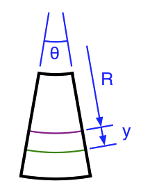
Let’s look more closely at the little section of beam bounded by the black lines.
The section is bent into a sort of wedge shape. We’ll call the angle of the wedge . The neutral surface is cylindrical with a radius of curvature that we’ll call .
Imagine a fiber embedded in the beam a distance below the neutral surface. The bending of the beam causes that fiber to stretch, as shown by the green line. The strain in the fiber is defined as the amount of the stretch divided by the original length. Because the neutral surface is the same length it was before the beam was bent, its current length, , is the same as the green fiber’s original length, and we can write the formula for the strain in the green fiber as
where (epsilon) is the symbol commonly used for strain, and is the curvature of the neutral surface.
Now it’s time to move from strain to stress. Stress, , is defined as the internal force per unit area, and the relationship between stress and strain for a linearly elastic material is defined by this generalization of Hooke’s Law:
where is the material’s modulus of elasticity, a measure of the material’s springiness. A higher value of means a stiffer material.
Substituting our expression for strain into this equation gives
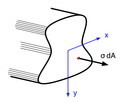
We now have enough information to figure out the location of the neutral surface. Every little differential piece of the cross section, , is acted upon by a force equal to .
Therefore, the net force, , acting over the entire cross-sectional area is equal to this integral:
Because there is no net force on the cross section, , and the integral in the last expression must be zero:
The origin of the axis, which is on the neutral surface, must be positioned so that this equation is true. This is, by definition, at the centroid of the cross section. The centroid of most common shapes can be looked up in tables, saving us the trouble of performing an integral.
Now it’s time to determine the relationship between the applied moment and the internal stress. The stress acting on each differential area of the cross section contributes to the total moment. The total moment, then, is
The integral in the last expression is known as the second moment of area or moment of inertia of the cross section, and is usually given the symbol . As with centroids, moments of inertia of common shapes can be looked up in tables.
The relationship between moment and curvature,
can be rearranged as
which tells us that the higher the moment of inertia of the cross section, the less the beam bends under a given load. We’ll return to this later.
Combining our expression for moment,
with our expression for stress,
we get
The maximum stress occurs when is at a maximum, that is, at the furthest distance within the cross section from the centroid.
where is called the section modulus of the cross section. The larger the section modulus, the lower the stress for a given load. You will be shocked, I’m sure, to hear that it can be looked up in tables for common shapes.
Perhaps the most common cross-sectional shape is the rectangle. A rectangle with base and height has a moment of inertia of
and a section modulus of
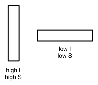
From these formulas, we see that the height is more important than the base in making a beam stiff and keeping its stress low. That’s why rectangular beams are usually oriented vertically instead of horizontally.
A standard wooden 2×8 (which is actually 1½″ by 7¼″) has a moment of inertia of 47.6 in4 and a section modulus of 13.1 in3 when oriented upright, but a moment of inertia and section modulus of only 2.04 in4 and 2.72 in3 when oriented flat.
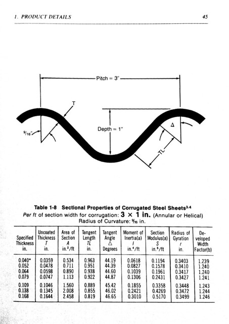
Another way to get a higher moment of inertia and section modulus out of a given amount of material is to corrugate it. A flat plate can be made much stiffer and stronger by forming its cross section into a wavy shape.
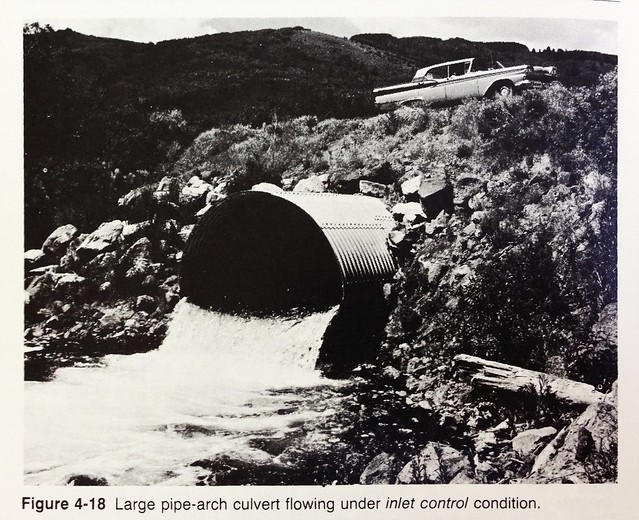
One of the many improbable books I own is the 1983 edition of the Handbook of Steel Drainage & Highway Construction Products from the American Iron and Steel Institute
The first edition of the Handbook came out in 1967, which explains the bitchin’ car up on the bridge.
Here’s a table of cross-sectional properties for a particular corrugation pattern:
Looking at the properties for the 0.109″ thickness, we see that a one-foot width of this corrugation has a moment of inertia of 0.1855 in4 and a section modulus of 0.3358 in3. In contrast, a flat plate of the same thickness would have a moment of inertia and section modulus of only 0.001144 in4 and 0.02188 in3, respectively. The corrugated section is two orders of magnitude stiffer and has an order of magnitude lower stress.
Which leads us, finally, to the structural design of potato chips. Ruffles have ridges because that makes them stronger in bending, just like the corrugated pipe.
(Image from Frito Lay.)
But you get that extra strength only when the ridges run perpendicular to the direction of bending. If you bend it in the other direction, the cross section is basically flat, and the moment of inertia and section modulus are no better than in a regular chip. Note how the good folks at Frito Lay show you right on the package the proper way to plunge a Ruffle into a bowl of dip. I can’t tell you how sad I feel when I see an otherwise intelligent person dip their Ruffle the wrong way and break the chip off.
This holiday season, I’ll be bringing my copy of the Handbook of Steel Drainage & Highway Construction Products to parties so I can explain. I’m betting I’ll soon have the dip all to myself.
-
The Euler is Leonhard Euler, of fame. The Bernoulli is Jacob Bernoulli, who developed the calculus of variations. (He was also the uncle of Daniel Bernoulli, whom we’ve met before.) The two of them, a generation apart, worked out the equations of the elastic curve, which governs the shape of a bent beam. ↩
-
There are other ways to ensure bending in one direction only, but they’re hard to understand before you’ve gone through the symmetric case. ↩
-
How good is this assumption? More rigorous analysis (which we won’t be attempting here) shows that it is exact only when the beam is in pure bending. It is, however, still quite accurate for other loading conditions. ↩
-
The modulus of elasticity is also commonly called Young’s modulus in honor of Thomas Young. ↩
-
Yes, that’s an affiliate link, because I know you’re all going to rush out and buy it, and I can’t resist the ensuing riches that will be mine for the taking. ↩


